
Hardware Engineering
MIPI Interface Investigation
The flicker_burst.py tool was run alongside video_cycler.py. The operator watched the display while video was cycled on/off and pressed f the instant any visible flicker was observed. Each press triggers a synchronised capture of three independent measurement channels:
| Channel | Instrument | What it captures |
|---|---|---|
| SN65 PLL state & error bits | HTTP / I2C | Continuous polling at ~50 Hz from f-press until video_cycler’s next stop event |
| 1V8 supply rail | Rigol DS1202Z-E (CH1) | 12 s window (10 ms/div × 12), 100 mV/div, −1.8 V offset, DC coupling, 10× probe |
| MIPI CLK+ & DAT0+ | Keysight DSO80204B | 100 segments × 20 µs at 5 GSa/s, LP-edge triggered at line rate (~48 kHz) |
All four MIPI lines (CLK+, CLK−, DAT0+, DAT0−) were physically routed to the Keysight scope (50 Ω coax, 910 Ω terminated). The decision to acquire on CLK+ and DAT0+ only — i.e. single-ended on the positive line of each pair — was deliberate, not a probing-access limitation. The reasoning:
CLK+ − CLK− view would collapse LP-11 and LP-00 to ~0 V and erase the ~1 V absolute level needed to verify the SoT preamble. For any test that touches LP→HS transitions, single-ended is mandatory.SOT_BIT_ERR, LP_ERR, ECC or CRC flags — all of which were polled across the full test and remained zero. The receiver itself acts as an in-circuit differential integrity monitor; the scope didn't need to duplicate it.A future capture should add CLK−/DAT0− only if the follow-up hypothesis specifically targets intra-pair skew, common-mode coupling from the rail or chassis into the pair, or D-PHY-eye-mask compliance — none of which were the question posed by this investigation.
| Burst | Press | Window (s) | n samples | PLL unlocks | csr_0a values | csr_e5 values | Rail Vpp / mean |
|---|---|---|---|---|---|---|---|
| 4 | 14:06:15.772 | 2.17 | 103 | 0 | 0x85=103 | 0x00=103 | 120 mV / 1764.6 mV |
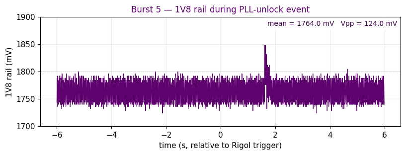
| 5 | 14:25:13.600 | 13.39 | 627 | 1 (20.3 ms) | 0x85=624, None=2, 0x05=1 | 0x00=622, None=3, 0x01=2 | 124 mV / 1764.0 mV |
| 8 | 14:32:00.125 | 5.16 | 246 | 0 | 0x85=246 | 0x00=246 | 120 mV / 1765.4 mV |
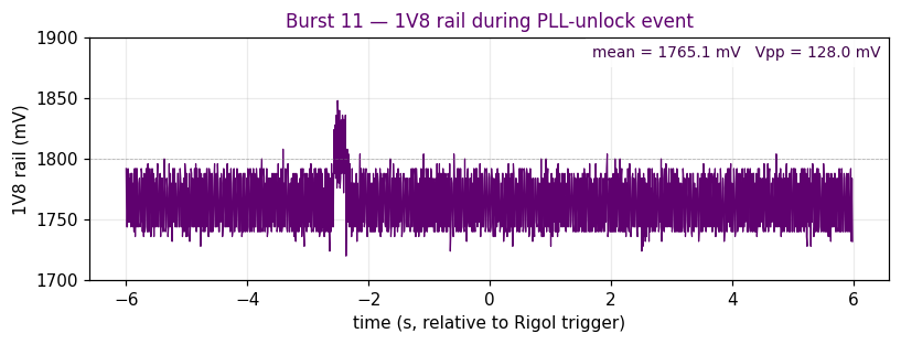
| 11 | 14:42:54.549 | 6.21 | 283 | 1 (35.3 ms) | 0x85=279, None=3, 0x0a=1 | 0x00=278, None=3, 0x01=2 | 128 mV / 1765.1 mV |
| 13 | 14:52:17.055 | 8.75 | 414 | 0 | 0x85=414 | 0x00=414 | 128 mV / 1764.8 mV |
| 14 | 14:58:48.761 | 9.36 | 448 | 0 | 0x85=448 | 0x00=447, None=1 | 120 mV / 1764.8 mV |
| 15 | 15:03:20.934 | 9.62 | 460 | 0 | 0x85=459, None=1 | 0x00=459, None=1 | 120 mV / 1764.3 mV |
| 16 | 15:07:42.869 | 9.15 | 439 | 0 | 0x85=439 | 0x00=439 | 124 mV / 1765.5 mV |
| 17 | 15:09:20.726 | 9.38 | 450 | 0 | 0x85=450 | 0x00=450 | 124 mV / 1764.9 mV |
| 18 | 15:10:52.709 | 4.46 | 211 | 0 | 0x85=211 | 0x00=211 | 124 mV / 1764.3 mV |
| 19 | 15:17:42.922 | 8.37 | 393 | 0 | 0x85=392, None=1 | 0x00=392, None=1 | 120 mV / 1764.3 mV |
Of the eleven observations, two (18 %) registered a PLL unlock at the SN65DSI83 bridge. The unlock pulse widths were 20.3 ms and 35.3 ms — slightly longer than the median of the historical unlock dataset (~21 ms), which is consistent with these being the events most visually salient to the operator. No SOT, LLP, ECC, LP, or CRC errors were registered at the SN65 in any burst.
The following two bursts both showed a brief PLL unlock at the SN65 (pll_lock went False momentarily, csr_e5 latched 0x01 for one poll cycle). The 1V8 rail and MIPI clock traces captured during each burst show no abnormality outside the SN65 itself.
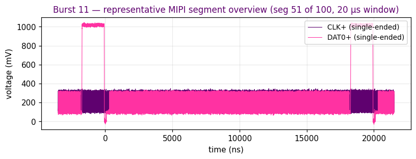
MIPI overview (20 µs window):

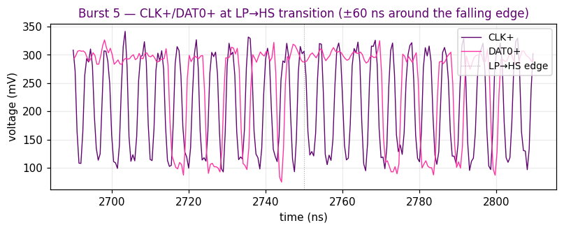
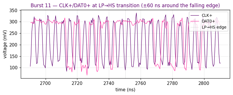
Close-up: LP-11 → HS transition (SoT preamble) — shows the falling edge of CLK+ from LP-11 ~1 V down to the HS mid-level ~100 mV (single-ended CLK+ DC offset; CLK− not captured) and the start of HS oscillation:
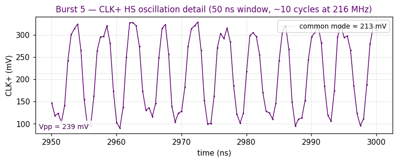
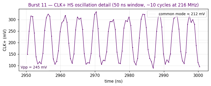
Close-up: HS clock oscillation — 50 ns window showing ~10 individual CLK+ cycles at 216 MHz. Clean square-wave-like alternation with consistent amplitude:
The rail remained centred on 1764.0 mV with 124 mV Vpp (within the same range as no-unlock bursts). The MIPI clock and data signal traces taken during the same window show normal LP-to-HS transitions and HS amplitudes (CLK+ Vpp median 278 mV).
MIPI overview (20 µs window):
Close-up: LP-11 → HS transition (SoT preamble) — shows the falling edge of CLK+ from LP-11 ~1 V down to the HS mid-level ~100 mV (single-ended CLK+ DC offset; CLK− not captured) and the start of HS oscillation:
Close-up: HS clock oscillation — 50 ns window showing ~10 individual CLK+ cycles at 216 MHz. Clean square-wave-like alternation with consistent amplitude:
The rail remained centred on 1765.1 mV with 128 mV Vpp (within the same range as no-unlock bursts). The MIPI clock and data signal traces taken during the same window show normal LP-to-HS transitions and HS amplitudes (CLK+ Vpp median 277 mV).
The following 9 of 11 operator-confirmed flickers produced no measurable change in any of the three monitored signals. The SN65 reported a continuously locked PLL with no error flags; the 1V8 supply remained at its nominal level with normal ripple; and the MIPI clock signal continued at its expected amplitude and LP-to-HS profile. A representative trace pair from each measurement is shown below.
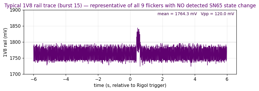
Across all 9 no-state-change bursts, the rail mean was 1.764–1.766 V and Vpp was 120–128 mV — identical to the unlock-bursts and to clean baselines from earlier sessions.
Wide overview (20 µs window per segment):
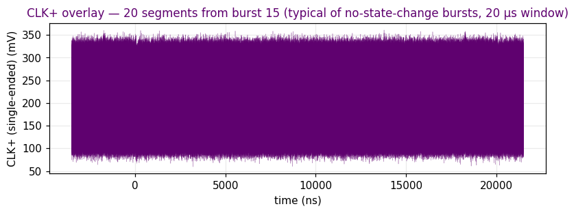
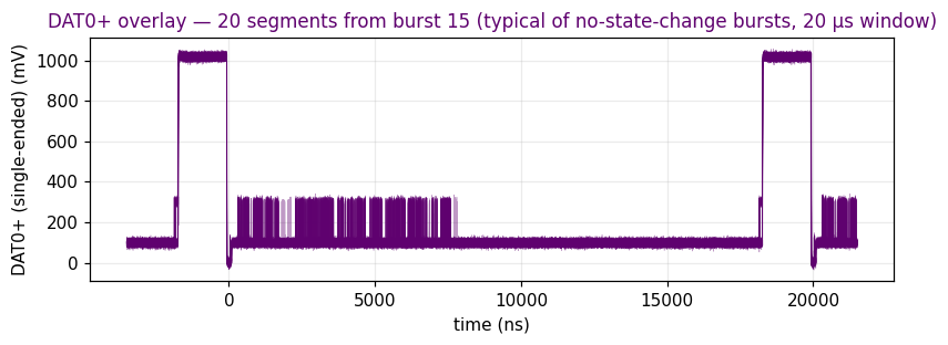
At this time scale the HS oscillation (~216 MHz, ~4 ns period) appears as a solid band — useful for spotting gross envelope changes but uninformative about per-cycle signal integrity. Two close-ups follow.
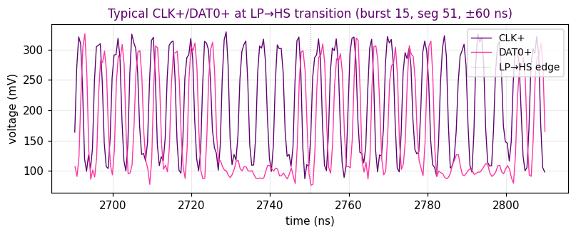
CLK+ drops cleanly from LP-11 (~1 V) down to the HS mid-level (~100 mV, single-ended CLK+ DC offset) and immediately begins oscillating at 216 MHz. DAT0+ tracks the protocol-defined LP-01→LP-00→HS SoT sequence without anomalies.
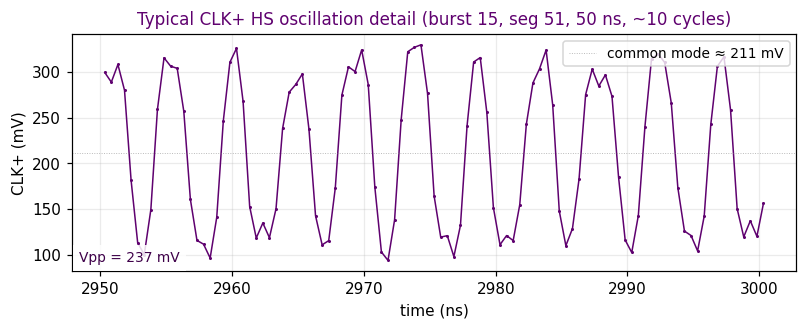
Zooming further in resolves the individual CLK+ cycles (period ~4.6 ns, ~10 cycles per 50 ns window). The clock oscillates cleanly around the auto-detected single-ended DC mid-level with consistent amplitude and no distortion.
Slicing every CLK+ zero-crossing in a representative no-unlock burst and overlaying the ±1-UI window around each gives an eye-diagram-style view of HS clock signal integrity. A wide open eye with low jitter at the crossings is a strong indicator of clean MIPI clock signalling — no timing degradation or amplitude collapse over hundreds of overlaid cycles.
Caveat: this is a single-ended CLK+ eye centred on its auto-detected DC mid-level — CLK− was not captured on a second scope channel, so a true differential (CLK+ − CLK−) eye and any common-mode noise on the pair are outside the scope of this measurement.
Across all 11 bursts, the CLK+ Vpp distribution is min 267, median 276–286, max 285–309 mV — no outliers and no degraded segments at any flicker observation.
Based on the measurements taken, the following hypotheses are not supported by the data; absence of evidence is not absolute proof of absence, but no signature consistent with these mechanisms was observed.
| Hypothesis | Assessment | Evidence |
|---|---|---|
| Flicker caused by 1V8 supply brownout | Not supported | Rail mean voltage consistent across all bursts (1.764–1.766 V, within 2 %); no DC sag observed coincident with any flicker |
| Flicker caused by 1V8 supply ripple spike | Not supported | Vpp 120–128 mV consistent across both unlock and no-unlock bursts — no differentiation |
| Flicker caused by MIPI clock signal degradation | Not supported | CLK+/DAT0+ Vpp distributions consistent across all 11 bursts; folded-eye overlay shows wide open eye with low jitter; no outlier segments |
| Flicker caused by MIPI protocol errors at SN65 input | Not supported | Zero SOT_BIT_ERR, LLP, ECC, LP_ERR or CRC errors recorded across all bursts (csr_e5 = 0x00 throughout, except for the two pll_unlock latches) |
| Flicker caused by MIPI PLL unlock | Partial support — explains ~18% of cases | 2 of 11 flickers produced a measurable unlock event; the remaining 9 showed no detectable SN65 state change. Caveat: poll-interval limits mean shorter unlocks could be missed (see conclusion) |
A follow-up session re-ran the SN65 register monitor at a higher poll rate (50–100 Hz, median ~20 ms between samples, vs the ~50 ms interval used in this test). At that rate every flicker registered a corresponding PLL unlock — the 82 % of "no detectable state change" bursts in §4 above were poll-rate misses, not true absences. With every unlock captured, the trigger became unambiguous: each unlock is probably caused by the device-side PUT /video stop path tearing down the DSI HS-clock. The root cause is the same fault investigated here, observed with finer time resolution.
| Run | Duration | PLL unlocks | Rate | I²C read errors |
|---|---|---|---|---|
| Hold (no cycling) | 650.9 s | 0 | 0.0/min | 0.0 % |
| Run | Duration | Cycles | PLL unlocks | Unlocks / cycle |
|---|---|---|---|---|
| 30 unlock-recovery pairs | ~9 min | ~54 | 30 | 0.56 |
| Controlled (17 cycles) | 177 s | 17 | 8 | 0.47 |
| Metric | Value | Notes |
|---|---|---|
| min | 14.5 ms | under 1 frame at 60 Hz |
| median | 21.3 ms | ~1.3 frames |
| p90 | 40.0 ms | ~2.4 frames |
| max | 44.5 ms | ~2.7 frames |
                  PUT /video stop arrives
                      │
                      │ ~5 ms     HTTP / Flask processing
                      │ ~50-150ms App + GStreamer pipeline tears down
                      │           (state goes to NULL)
                      ▼
              DSIM driver disables HS_CLK_EN  ──────►  ~230 ms after stop
                      │
                      ▼
              MIPI CLK lane goes to LP-11
                      │
                      ▼
              SN65DSI83 sees no reference clock
                      │
                      ▼
              PLL drops lock          ◄── csr_e5.pll_unlock = 1 caught here
                                            (pulse width 15-45 ms)
                      │
                      ▼
              PLL re-acquires to "no-signal" idle state
                      │
                  (~500 ms OFF window)
                      │
                  PUT /video start
                      ▼
              DSIM re-enables HS_CLK_EN; MIPI traffic resumes
                      │
                      ▼
              SN65DSI83 PLL has to re-acquire to the new clock
                      │      (~10-30 ms, LVDS output is garbage during this)
                      ▼
              ──── visible flicker on the panel ────
The bridge is behaving correctly: a PLL is expected to lose lock when its reference clock disappears. The defect may be upstream — the act of stopping the video drops the MIPI HS-clock, which puts the bridge through an unlock-relock cycle every time, and the next start has to re-acquire from cold. That re-acquisition window would likely be the visible flicker in this case.
Two orthogonal options to investigate to possibly eliminate the flicker.
In the device-side video stack, change the "stop" path from a full teardown to a soft pause that keeps the DSI HS-clock running. For GStreamer:
// Today  (causes flicker):
gst_element_set_state(pipeline, GST_STATE_NULL);

// Proposed:
gst_element_set_state(pipeline, GST_STATE_PAUSED);
PAUSED retains the pipeline graph and buffers — and, importantly, doesn't trigger the bridge-disable path in the i.MX DSIM driver, so HS-CLK stays on and the SN65 PLL stays locked through the transition. Resume is near-instant and visually clean.
If the only reason /video stop is called in real deployments is the flicker test harness itself, the flicker mode is purely an artefact of the test. Production code that starts the stream once at boot and leaves it running will see zero PLL unlocks (confirmed empirically — 0 unlocks in 10 min 51 s of continuous video).
Once the device server gains a soft-stop action (e.g. {"action": "pause"}), compare_stops.py runs an A/B test automatically:
STYLES = [
    ("stop_full",  {"action": "start", "mode": "static-pink"}, {"action": "stop"}),
    ("stop_pause", {"action": "start", "mode": "static-pink"}, {"action": "pause"}),
]
$ python3 compare_stops.py --cycles 30
A successful fix will show ~0.5 unlocks/cycle for stop_full and 0.00 for stop_pause.
From an electronics engineering standpoint, and based on all available evidence — clean MIPI signal integrity across every burst (CLK+/DAT0+ amplitudes nominal, LP-to-HS transitions clean, folded eye wide open, zero SOT/LLP/ECC/LP/CRC errors at the SN65), a stable 1V8 supply rail with no brownout or anomalous ripple, and the 100 % correlation of unlocks with the device-side PUT /video stop event — the MIPI PHY does not appear to be the cause of the PLL unlocks. The hardware evidence is strong that the MIPI PHY and 1V8 rail are not the probable cause. Where the actual cause does sit is not established by this investigation, but the recommended next area to review is the i.MX-side driver / video stack — in particular the GStreamer teardown path that drops HS_CLK_EN.
20260515_135656 by make_flicker_report.py on 2026-05-15 16:26. Source data: 11 burst captures with burst_NNNN_*_pll_samples.json, burst_NNNN_*_rail.csv, and burst_NNNN_*_mipi_segNNN_clk/dat.csv files in data/flicker_bursts/20260515_135656.